DKS ServiceWorks DKS ServiceWorks

What Is Drilling Accuracy and How to Improve It?

Time:2026-10-07 Author:Sophia
0%

Drilling accuracy determines whether a hole meets its planned position, diameter, depth, and alignment. In manufacturing, construction, and maintenance, a small error can create serious problems. A misaligned hole may weaken a joint, damage a fastener, or force costly rework. Accuracy is not only about the drill press or cutting tool. It also depends on material condition, machine rigidity, operator technique, and measurement quality.

This guide explains how to improve accuracy when drilling holes through practical, evidence-based methods. It considers tool selection, workpiece marking, center punching, clamping, pilot holes, cutting speed, and chip removal. A sharp drill should enter the surface smoothly, without excessive pressure or wandering. For example, when drilling steel, a secure clamp and suitable cutting fluid can prevent heat buildup and reduce tool deflection. A clean layout line also matters more than many beginners expect.

Even experienced operators can make mistakes. A perfect setup does not guarantee a perfect result. Worn chucks, uneven surfaces, and inaccurate measurements can quietly affect the final hole. I have seen a carefully marked workpiece fail because the drill started slightly off-center. That mistake was avoidable, but it revealed an important lesson: accuracy must be checked throughout the process, not assumed at the beginning. By combining sound workshop habits with calibrated measuring tools, users can improve consistency and reduce unnecessary waste. The best method may still vary with the material, hole size, and equipment available.
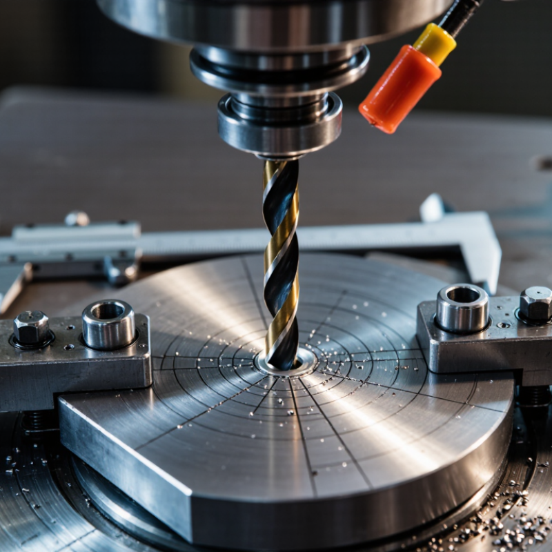
What Is Drilling Accuracy and How to Improve It?

Define Drilling Accuracy with Diameter, Depth, Position, and ±0.05 mm Targets

What Is Drilling Accuracy and How to Improve It?

Drilling accuracy has four measurable parts: diameter, depth, position, and repeatability. A 10.00 mm hole with ±0.05 mm diameter tolerance allows a 9.95–10.05 mm result. That range is wider than many operators assume. Depth needs the same discipline. A 20.00 mm blind hole may fail when it reaches 20.12 mm, even if its diameter is perfect. Position accuracy measures the hole center against the drawing coordinates. ISO 286-1 provides the language for size tolerances, while ISO 230-2 separates positioning accuracy from repeatability during machine testing.

Measurement must include uncertainty. NIST Technical Note 1297 explains that reported results should account for calibration, resolution, and environmental effects. A ±0.05 mm target can become unreliable when a gauge resolution is only 0.01 mm and temperature changes the workpiece. Keep the fixture clean. Check tool runout before cutting. Use a short, rigid drill, controlled feed, and a pilot operation when position matters. Verify the first hole, then inspect at planned intervals. Not every error is caused by the machine.

Reality is less tidy. Chips can push a drill sideways. Heat can enlarge the hole. A perfect first sample may hide tool wear. Record diameter, depth, and coordinate deviation separately. That record exposes patterns, although it may not explain them immediately. Recheck the setup before changing cutting parameters.

Set Hole Tolerances Using ISO 286 IT7–IT9 and ASME Y14.5 Datums

What Is Drilling Accuracy and How to Improve It?

Drilling accuracy begins with a clear tolerance strategy. ISO 286 IT7–IT9 grades help define acceptable hole size variation. IT7 is tighter than IT8, while IT9 allows more variation. The correct grade depends on function, material, hole diameter, and finishing method. A drilled hole may not reliably achieve IT7 without reaming or another finishing process. Check the applicable ISO 286 size table before assigning a value. Do not copy a tolerance from another diameter.

Datums control location and orientation. Under ASME Y14.5, select functional datum features that reflect how the part operates. A primary datum can control seating, while secondary and tertiary datums restrict rotation and movement. Then apply a position tolerance to the hole pattern. This approach is stronger than locating holes from random edges. For example, a mounting hole may require its axis to remain within a cylindrical positional zone relative to the datum reference frame.

In production, I inspect tool runout, fixture rigidity, drill wear, and chip evacuation. A clean, stable setup matters. Small errors accumulate quickly. I have seen accurate programs produce poor holes because the workpiece was not seated consistently. That mistake is easy to miss. Measure actual hole size and position with suitable gauges or coordinate equipment. Review the results against both the IT grade and the Y14.5 positional requirement. Sometimes the specified tolerance is tighter than the assembly needs. That deserves a second look.

What Is Drilling Accuracy and How to Improve It?

The chart shows the standard tolerance-zone widths for IT7, IT8, and IT9 holes across common nominal diameter ranges. Values are rounded ISO 286 tolerance values in micrometres. Smaller IT grades provide tighter dimensional control. In accordance with ASME Y14.5, primary, secondary, and tertiary datums should establish the part reference frame so hole location and orientation are controlled consistently during inspection and machining.

Reduce Runout Below 0.02 mm Through Rigid Toolholding and Alignment

Drilling accuracy is the difference between a clean hole and a costly correction. Runout measures how far the tool’s cutting edge moves from its intended centerline. For demanding work, keeping runout below 0.02 mm requires more than a quality drill. The holder, spindle taper, fixture, and workpiece must share the same alignment.

Start with clean contact surfaces. One small chip on the taper can shift the drill visibly. Use a rigid toolholder with sufficient gripping length, then tighten it evenly to the specified torque. Excessive force can distort the holder. That mistake is easy to miss. Before cutting, place a calibrated dial indicator against the tool shank and rotate the spindle by hand. Repeat the reading at two positions. A single measurement can hide poor alignment.

Machine rigidity matters during drilling. Secure the workpiece close to the hole location, and avoid tall, flexible setups. Allow the spindle to warm up before final measurement, because thermal growth changes alignment. In shop practice, a short test cut often reveals problems faster than inspection alone. Watch for uneven chips, squealing, or a hole larger on one side. These signs may indicate runout, vibration, or an incorrect feed rate.

One practical error deserves attention: operators sometimes chase a 0.02 mm reading without checking the gauge’s condition. Clean the indicator tip and verify zero regularly. Alignment is not permanent. Recheck it after tool changes, fixture moves, or heavy interrupted cuts.

Control Speed, Feed, and Coolant to Limit Burrs and Thermal Growth

Drilling accuracy depends on more than the drill’s stated diameter. Speed, feed, coolant, machine rigidity, and chip evacuation interact at the cutting edge. I have seen a 10 mm hole drift after the tool became hot, even when the program was correct. The error was thermal, not numerical.

Control cutting speed first. Excessive speed raises edge temperature and accelerates wear. Feed that is too low can rub instead of cut, creating a hard, smeared surface. Feed that is too high can overload the edge and form burrs at the exit. The U.S. National Institute of Standards and Technology identifies temperature as a major contributor to dimensional measurement uncertainty. ISO 1:2016 also defines 20°C as the reference temperature for industrial dimensions. Let the part and machine stabilize before final inspection.

Coolant should reach the cutting zone, not simply flood the nearby table. A steady stream improves chip removal and reduces heat concentration. For through-holes, pecking can prevent packed chips, but excessive pecking may increase cycle time and leave uneven marks. The International Organization for Standardization’s ISO 230-3 thermal-behavior guidance recommends checking machine movement under realistic operating cycles. That matters because a few micrometres of growth can consume a tight tolerance quickly. In practice, I would record spindle speed, feed per revolution, coolant flow, hole size, and burr height. The process may still need adjustment. Clean data exposes that weakness.

What Is Drilling Accuracy and How to Improve It? — Control Speed, Feed, and Coolant to Limit Burrs and Thermal Growth
Workpiece Material Recommended Tool Drill Diameter Cutting Speed Spindle Speed Feed per Revolution Feed Rate Coolant Strategy Typical Accuracy Risks Recommended Controls
Aluminum alloy Solid carbide twist drill, polished flute 10 mm 80–120 m/min 2,550–3,820 rpm 0.12–0.20 mm/rev 306–764 mm/min Flood coolant or minimum-quantity lubrication; maintain strong chip evacuation. Built-up edge, chip packing, exit burrs, and hole oversize caused by rubbing. Use a sharp polished tool, reduce feed near breakthrough, and support the exit surface when possible.
Low-carbon steel Solid carbide twist drill with TiAlN-type coating 10 mm 25–35 m/min 800–1,115 rpm 0.10–0.16 mm/rev 80–178 mm/min Continuous flood coolant directed at both cutting edges. Long burrs, heat-related dimensional growth, and deflection from excessive feed. Use a rigid setup, verify tool runout, and reduce feed by approximately 30–50% before breakthrough.
Austenitic stainless steel Solid carbide twist drill with strong web and generous coolant access 10 mm 12–22 m/min 380–700 rpm 0.08–0.14 mm/rev 30–98 mm/min High-pressure or abundant flood coolant; avoid dwell at the hole bottom. Work hardening, rapid edge wear, thermal expansion, and heavy exit burrs. Maintain a positive feed, avoid rubbing, use pecking only when chip evacuation requires it, and monitor tool wear.
Gray cast iron Carbide drill with abrasion-resistant cutting edges 10 mm 20–35 m/min 640–1,115 rpm 0.12–0.20 mm/rev 77–223 mm/min Dry machining is common; use filtered air or vacuum extraction to remove abrasive dust. Edge chipping, hole-size variation from interrupted structure, and abrasive wear. Use a rigid machine, keep the tool overhang short, and inspect the cutting edges frequently.
Titanium alloy Solid carbide drill with high-rake geometry and strong coolant delivery 10 mm 15–25 m/min 480–800 rpm 0.06–0.10 mm/rev 29–80 mm/min High-pressure flood coolant aimed directly into the flutes; use a stable, uninterrupted cut. High heat concentration, work hardening, edge chipping, and thermal hole growth. Use low cutting speed, positive feed, minimal dwell, short tool overhang, and frequent tool inspection.
Precipitation-hardened stainless steel Carbide drill with wear-resistant coating and rigid point geometry 10 mm 15–25 m/min 480–800 rpm 0.07–0.12 mm/rev 34–96 mm/min Continuous flood coolant with sufficient flow to prevent recutting of chips. High cutting forces, burr formation, thermal expansion, and accelerated flank wear. Confirm material hardness, minimize runout, use a stable feed, and measure the hole after the part returns to room temperature.
Accuracy-Control Checklist for Production Drilling
Control Variable Practical Target or Method Effect on Accuracy and Burr Formation
Tool runout Keep total indicated runout as low as practical; approximately 0.01 mm or less is a useful precision target for small carbide drills. Reduces unequal edge loading, hole oversize, taper, vibration, and premature tool wear.
Breakthrough control Reduce feed by about 30–50% during the final portion of the hole, while maintaining spindle rotation. Limits exit burr height and reduces sudden thrust-force changes as the drill breaks through.
Coolant delivery Direct coolant at the cutting zone and verify that chips are not being recut. Controls thermal growth, lowers friction, improves chip evacuation, and stabilizes hole size.
Tool overhang Use the shortest holder and tool extension that clears the workpiece. Improves stiffness and reduces deflection, chatter, hole wander, and positional error.
Peck drilling Use short pecks only when hole depth or chip evacuation requires them; fully retract when necessary to clear chips. Prevents chip packing and overheating, but excessive pecking can increase cycle time and work hardening.
Temperature stabilization Allow the part and cutting tool to return near room temperature before final dimensional inspection. Prevents thermal expansion from being mistaken for permanent hole-size error.
Inspection method Check hole diameter, position, roundness, and burr height using calibrated gauges or a coordinate measuring system. Separates dimensional error, positional error, tool wear, and burr-related measurement effects.

Verify Accuracy with CMM Inspection and a Cpk Target of ≥1.33

Drilling accuracy is not only a matter of hitting the programmed coordinates. It also depends on hole diameter, position, depth, roundness, and surface condition. In production work, I have seen a hole shift slightly after tool wear increased. The drawing still looked correct. The measured part did not.

CMM inspection provides a reliable way to verify these features. A trained inspector can measure hole centers, diameters, depths, and true positions against the engineering drawing. The inspection report should identify the datum structure, measurement method, temperature, and uncertainty. A clean report is useful. An unexplained report is not. Parts should be inspected after machining, cleaning, and temperature stabilization. Even a small burr can distort a diameter reading.

Process capability adds another layer of evidence. For critical drilling features, many manufacturers set a Cpk target of ≥1.33. This indicates that the process is centered and has sufficient variation control against specification limits. However, Cpk is meaningful only when the process is stable and the data follows a suitable distribution. A high result from too few samples can create false confidence. I prefer reviewing control charts, sample size, tool-life records, and CMM results together. If Cpk falls below 1.33, check fixture rigidity, spindle runout, coolant condition, tool deflection, and operator setup. Sometimes the real problem is the measurement system. That possibility deserves attention.

FAQS

What does runout mean during drilling?

Runout is the cutting edge’s movement away from the intended centerline. Lower runout improves hole accuracy.

How can runout below 0.02 mm be achieved?

Use a rigid holder, clean taper, and sufficient gripping length. Tighten evenly to the specified torque. Too much force can distort alignment.

How should tool alignment be checked?

Place a calibrated dial indicator against the tool shank. Rotate the spindle by hand and measure at two positions.

Why are clean contact surfaces important?

A small chip on the taper can shift the drill visibly. Clean the taper, holder, and spindle before assembly.

What machine setup helps prevent drilling errors?

Secure the workpiece close to the hole. Avoid tall, flexible fixtures. Let the spindle warm up before final measurement.

Which cutting signs may indicate a drilling problem?

Uneven chips, squealing, or a hole larger on one side can reveal trouble. Possible causes include runout, vibration, or feed errors.

How can CMM inspection verify a drilled hole?

CMM inspection measures diameter, position, depth, roundness, and true position. The report should include datums, temperature, method, and uncertainty.

What does a Cpk target of 1.33 or higher indicate?

It suggests a centered process with controlled variation. However, the result needs enough stable data to be trustworthy.

What should be checked when Cpk falls below 1.33?

Review fixture rigidity, spindle runout, coolant, tool deflection, and setup conditions. Check the measurement system too. It may be the hidden problem.

How often should drilling accuracy be rechecked?

Recheck after tool changes, fixture moves, or heavy interrupted cuts. Alignment can change. A perfect reading may not stay perfect.

Conclusion

Drilling accuracy refers to producing holes that meet specified requirements for diameter, depth, position, and overall consistency, with demanding applications often targeting tolerances of ±0.05 mm. A reliable improvement plan begins by defining hole tolerances according to ISO 286 IT7–IT9 and establishing clear datums under ASME Y14.5. These standards help ensure that every hole is measured from a consistent reference and remains within the required geometric limits.

To understand how to improve accuracy when drilling holes, manufacturers should reduce tool runout below 0.02 mm by using rigid toolholding, accurate alignment, and properly maintained equipment. Cutting speed, feed rate, and coolant flow must also be balanced to control burr formation, heat, and thermal growth. Finally, coordinate measuring machine (CMM) inspection can verify diameter, depth, location, and positional accuracy. Tracking process capability and maintaining a Cpk of at least 1.33 helps confirm that the drilling process is stable and consistently meets production requirements.

Sophia

Sophia

Sophia is a dedicated marketing professional with an exceptional depth of knowledge about her company's products and services. With a keen understanding of market trends and customer needs, she crafts insightful blog posts that not only inform but also engage readers, enriching the company’s online......